Temperaturmessung
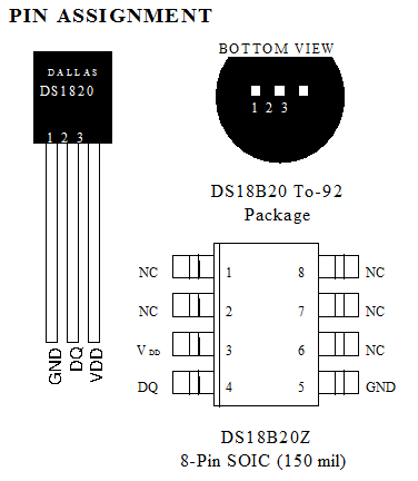
Sensoren: DS1820 bzw. DS18B20 am One wire bus.
Pullup: 4K7
Unterschied zwischen DS1820 und DS18B20
Beim DS1820 ist die Einheit des Temperaturwertes 0.5°C, beim DS18B20 ist es defaultmäßig 1/16°C = 0.0625°C. Entsprechend muss der ausgelesene Wert anders umgerechnet werden.
Beim DS18B20 kann die Auflösung geändert werden von 9-12 Bit. Bei 12Bit dauert die Messung 750ms, bei 9 Bit nur ca. 94ms.
Die Bits 6 und 5 im Konfigurationsregister (Byte 4 im Speicher) legen die Auflösung fest.
Temperaturmessung mit einem Sensor
                           'Thermometer mit DS18B20 1Wire  (12bit-Sensor)

                           'Pin1 GND, Pin3 an +5V, Pin2 Pullup 4K7 = Datenleitung am uC PortD.5

                           'Da der Sensor 750ms zum Messen braucht wird hier immer der vorige Wert übertragen


                           $crystal = 16000000

                           $regfile = "m8def.dat"

                           $hwstack = 50


                           $baud = 9600


                           'DS18B20

                           Dim Dsread(9) As Byte

                           Dim Itemperature As Integer At Dsread Overlay       'enthält Temp. in 0.0625°C

                           Dim Temperature As Single

                           Config 1wire = Portd.5


                           '------------------------------------------------------------------------------


                           Do

                                 Gosub Measuretemperature

                                 Print Temperature

                                 Wait 1

                           Loop

                           '------------------------------------------------------------------------------

                           Measuretemperature:

                           'gemessene Temperatur steht in Variable Temperature

                           '1wire muss vorher konfiguriert sein


                                 'Messen

                                 1wreset

                                 1wwrite &HCC                      'alle herhören

                                 1wwrite &H44                      'Messen

                                 Waitus 200


                                 'auslesen

                                 1wreset

                                 1wwrite &HCC

                                 1wwrite &HBE                      'RAM auslesen

                                 Dsread(1) = 1wread(9)             '9 Byte lesen


                                 Temperature = Itemperature * 0.0625


                           Return

                           '-------------------------------------------------------------------------------
Adresse des Sensors bestimmen
Jeder Sensor bekommt bei der Herstellung eine feste Adresse, unter der er angesprochen werden kann.
                           'Thermometer mit DS18B20 1Wire  (12bit-Sensor)

                           'Pin1 GND, Pin3 an +5V, Pin2 Pullup 4K7 = Datenleitung am uC PortD.5

                           'Adresse lesen


                           $crystal = 16000000

                           $regfile = "m8def.dat"

                           $hwstack = 50


                           $baud = 9600


                           'DS18B20

                           Dim Dsread(9) As Byte

                           Config 1wire = Portd.5


                           Dim I As Byte


                           '------------------------------------------------------------------------------


                           Do

                                 Gosub Displayaddress

                                 Wait 1

                           Loop

                           '------------------------------------------------------------------------------


                           Displayaddress:

                                 1wreset


                                 'skip ROM, also alle Bausteine ansprechen

                                 ' (es ist nur einer da also keine gezielte Adressierung nötig)


                                 1wwrite &HCC

                                 Dsread(1) = 1wsearchfirst()


                                 '8Byte   Adresse  hex. anzeigen

                                 For I = 1 To 8

                                     Print Hex(dsread(i));

                                 Next I

                                 Print

                           Return


                           '------------------------------------------------------------------------------
Mehrere Sensoren an einem Controller
Um die Ansteuerung zu vereinfachen, und einen problemlosen Austausch von Sensoren zu erlauben, werden diese nicht alle an einem Pin des Controllers angeschlossen, sondern jeder Sensor hängt an einem separaten Pin. So kann man die Sensoren über den Befehl &HCC ansprechen („alle herhören!), andernfalls müsste man die genaue Adresse der Sensoren kennen.
                           'Thermometer mit DS18B20 1Wire

                           'Pin1 GND, Pin3 an +5V, Pin2 Pullup 4K7 = Datenleitung am uC PortD.7 bzw. PortD.6

                           'mit Datenausgabe RS232 9600 Baud


                           $crystal = 16000000

                           $regfile = "m8def.dat"

                           $hwstack = 50


                           $baud = 9600


                           'DS1820

                           Config 1wire = Portd.7

                           Config 1wire = Portd.6

                           Dim Thpinnr As Byte                     'PinNr für die Auswahl der Sensoren

                           Dim Dsread(9) As Byte

                           Dim Itemperature As Integer

                           Dim Temperature As Single

                           Dim S As String * 5


                           '------------------------------------------------------------------------------


                           Do

                                 ' erster Sensor

                                 Thpinnr = 7

                                 Gosub Measuretemperature

                                 Print Temperature;

                                 Print Chr(9);


                                 ' zweiter Sensor

                                 Thpinnr = 6

                                 Gosub Measuretemperature

                                 Print Temperature;


                                 Print

                                 Wait 1


                           Loop


                           '------------------------------------------------------------------------------

                           Measuretemperature:

                           'Temperatur auslesen und in Variable Temperature schreiben

                           'vorher muss  Thpinnr gesetzt werden (Nummer des Pins an dem der Sensor hängt)

                                 'Messen

                                 1wreset Pind , Thpinnr

                                 1wwrite &HCC , 1 , Pind , Thpinnr 'alle herhören

                                 1wwrite &H44 , 1 , Pind , Thpinnr 'Messen

                                 Waitus 200


                                 'auslesen

                                 1wreset Pind , Thpinnr

                                 1wwrite &HCC , 1 , Pind , Thpinnr

                                 1wwrite &HBE , 1 , Pind , Thpinnr 'RAM auslesen

                                 Dsread(1) = 1wread(9 , Pind , Thpinnr )


                                 Itemperature = Makeint(dsread(1) , Dsread(2))


                                 Temperature = Itemperature * 0.0625


                           Return
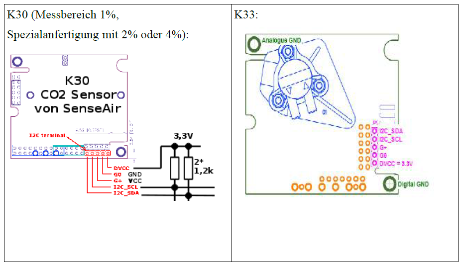
Kommunikation über I2C
Anschluss am I2C-Port des Controllers mit 1.2K- Pullup nach +3.3V
Beim K33 muss der Wert noch mit 10 multipliziert werden.
Testprogramm für CO2-Sensor:
Auslesen des Sensors und Daten über serielle Schnittstelle an einen PC schicken
                           'CO2-Messung<

                           'Sensor an I2C

                           'PC.5 = SCL

                           'PC.4 = SDA


                           $crystal = 8000000

                           $regfile = "m8def.dat"

                           $hwstack = 50


                           $baud = 9600

                           'Enable Urxc

                           'Enable Interrupts

                           'On Urxc Rscommand


                           Config Portd.5 = Output                 'LED


                           'I2C

                           Config Sda = Portc.4

                           Config Scl = Portc.5


                           'CO2-Sensor

                           Dim Sensorstatus As Byte

                           Dim Sensorvalue As Word

                           Dim Sensorvalue_h As Byte At Sensorvalue Overlay

                           Dim Sensorvalue_l As Byte At Sensorvalue + 1 Overlay

                           Dim Sensorchecksum As Byte


                           Dim Secs As Long

                           '-------------------------------------------------------------------------------

                           Main:

                           Do

                               Secs = Secs + 1


                               Gosub Measureco2


                               Print Secs;

                               Print Chr(9);

                               Print Sensorvalue;

                               Print Chr(9);

                               If Sensorstatus = 1 Then Print "OK" Else Print "Error"


                               Waitms 1000


                           Loop

                           '-------------------------------------------------------------------------------

                           Measureco2:

                           'Senseair K30-Sensor über I2C ansprechen

                           'auf Fehler prüfen (Sensor nicht bereit) durch Auslesen des Statusbytes

                           'falls nicht bereit: Sensorstatus =0, falls Ok: 1


                               I2cstart

                               I2cwbyte 0

                               I2cstop


                               Waitms 1


                               I2cstart

                               I2cwbyte &HD0                     'Adresse (&h68 1 Bit nach links, Bit0=R/W=0 (schreiben)

                               I2cwbyte &H22                     'Read RAM   2 Bytes

                               I2cwbyte &H00                     'Adresse H

                               I2cwbyte &H08                     'Adresse L

                               I2cwbyte &H2A                     'Checksum

                               I2cstop


                               Waitms 20


                               I2cstart

                               I2cwbyte &HD1                       'Lesen an Adresse &h68

                               I2crbyte Sensorstatus , Ack

                               I2crbyte Sensorvalue_l , Ack

                               I2crbyte Sensorvalue_h , Ack

                               I2crbyte Sensorchecksum , Nack

                               I2cstop


                               Sensorstatus = Sensorstatus And 1

                           Return
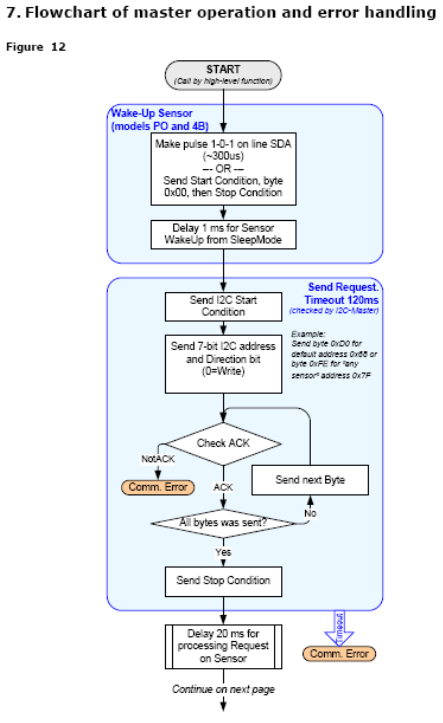
Unterlagen von Senseair zur Programmierung
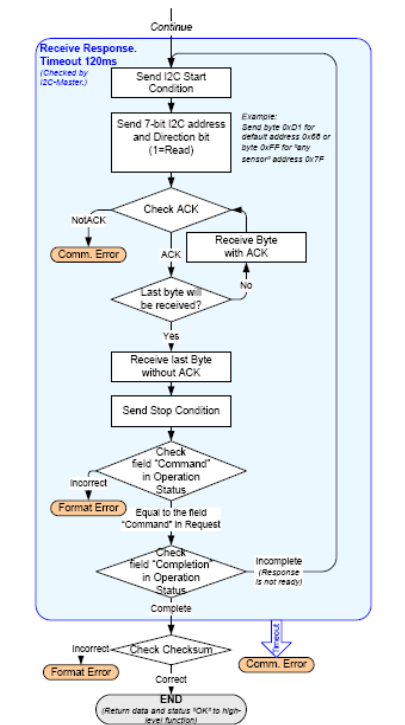
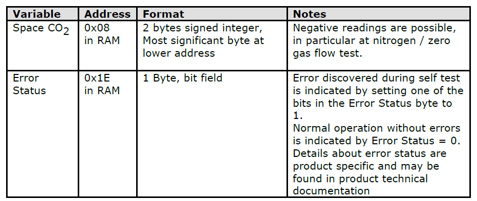
10.1. Example: Reading of CO2 value from sensor
To read the current CO2 concentration from the sensor we need to read memory locations 0x08 (hi byte) and 0x09 (low byte). To do this we need to send a sequence of two I2C frames: first we send an I2C write frame containing the sensor address, command number and how many bytes to read, RAM address to read from, and a checksum. Then we send an I2C read frame to read the status, data and checksum. See chapter 2 for details. In our case we want to read 2 bytes starting from address 0x08. This will give us data from address 0x08 and 0x09, which contains current CO2 reading. The sensor address is 0x68 (default factory setting, configurable in EEPROM). So, the first frame should look like:
Start | 0xD0 | 0x22 | 0x00 | 0x08 | 0x2A | StopA. a. 0xD0 is Sensor address and read/write bit. 0x68 shifted one bit to left and R/W bit is 0 (Write).
B. b. 0x22 is command number 2 (ReadRAM), and 2 bytes to read
C. c. Checksum 0x2A is calculated as sum of byte 2, 3 and 4.
II.
The next frame will read the actual data:
Start | 0xD1 | <4 bytes read from sensor> | Stop
A. d. The 1:st byte from the sensor will contain operation status, where bit 0 tells us if the read command was successfully executed.
B. e. The 2:nd and 3:rd byte will contain CO2 value hi byte and CO2 value low byte.
C. f. The 4:th byte contains checksum
D.
E.
F. 10.2. Example: Start background and zero calibration with I2C commands
III.
In K30 and K50 meters it is possible to start zero and background calibrations with I2C commands.
Background calibration for K30 meters look like this:
Start | 0xD0 | 0x12 | 0x00 | 0x67 | 0x7C | 0x06| 0xFB | Stop
A. a. 0xD0 is Sensor address and read/write bit. 0x68 shifted one bit to left and R/W bit is 0 (Write).
B. b. 0x12 is command number 1 (WriteRAM), and 2 bytes to write
C. c. 0x7C06 is background calibration command
D. d. Checksum 0xFB is calculated as sum of byte 2-6.
Zero calibration for K30:
I2C comm guide 2_10.doc Page 29 of 33
Start | 0xD0 | 0x12 | 0x00 | 0x67 | 0x7C | 0x07| 0xFC | Stop
1. e. 0xD0 is Sensor address and read/write bit. 0x68 shifted one bit to left and R/W bit is 0 (Write).
2. f. 0x12 is command number 1 (WriteRAM), and 2 bytes to write
3. g. 0x7C07 is background calibration command
4. h. Checksum 0xFC is calculated as sum of byte 2-6.
In K50 meters with memory map 8 or lower the zero and background commands are identical to K30 meters. In K50 meters with memory maps higher than 8 the address to write to is moved from 0x67, 0x68 to 0x32, 0x33.
Table 11 Measured value and status